 |
|
<< Click to show the Table of Contents >> MILLIMETER–WAVE PROPAGATION MODELS |


|
|
|
<< Click to show the Table of Contents >> MILLIMETER–WAVE PROPAGATION MODELS |
|
|
The evolution to 5G includes the possibility of using frequencies above 6 GHz, particularly in the millimeter wave bands. Although the specific frequencies will not be allocated by the ITU until the World Radiocommunication Conference in 2019, there are already previous studies underway and a first allocation carried out in the United States by the FCC, in which some bands close to 28 and 38 GHz have been allocated for use in the mobile service. At these frequencies there are propagation effects caused by the atmosphere (attenuation by gases or rain) and others due to the physical environment. The former are already incorporated into planning tools, since they also affect fixed microwave radio links that also use frequencies in the microwave and millimeter wave bands. Therefore, its incorporation into the new calculations is relatively straightforward. Regarding the effects of the environment, in recent years there has been a very intense research activity around the world to model propagation in millimeter bands in mobile systems. There are measurements published by European and North American universities, as well as companies and research organizations around the world. Various authors consider that the CI model (simpler and with a physical basis) is sufficient to describe propagation under LOS conditions. However, this model does not describe the first few meters well for NLOS conditions. The CIF and ABG models are considered multi-frequency and allow extrapolations to different operating frequencies. They also have double slope variants, which could be interpreted as a generalization. However, the usefulness of their use in contrast to the complexity they introduce may be questioned, since only some measurement campaigns have shown a marked double slope trend. These models assume the existence of a point of inflection (break point distance) in the measurements. The implementation of all of them in the planning tools can be very useful, allowing the user to select which one they want to use in each case. The available technical literature will also be studied to identify other available models. The models presented below have been specifically developed to operate at millimeter frequencies, although their operating range may reach lower frequencies. The 5GCM model is the one proposed by a group of universities and companies, presented in [2]. The 3GPP model is the one included in the 3GPP Report TR 38.901 [3]. The METIS [4] and mmMAGIC [5] models have been developed in these European projects. The scenarios analyzed are the Urban Microcell (UMi) [4] [5], the Urban Macrocell (UMa) [2] [3] and the Rural Macrocell (RMa) [6] [7]. In some of these cases there are more specific conditions such as the urban canyon (Urban canyon) made up of areas with tall buildings and the square (Open-square). In the case of rural cells, only the NYU (New York University) [6] [7] has been specifically developed for millimeter frequencies. The models in Report ITU-R M.2135-1 [8] and 3GPP TR 38.900 [9] have been adopted by ITU-R and 3GPP respectively for millimeter frequencies. These were not developed for these frequencies or for rural conditions, so their use is questionable [6]. FLOATING INTERCEPT MODEL (FI) The FI model was used in the development of the WINNER II and 3GPP channel models. It is a model without physical reference that simply finds the line that best fits the measured data using a least squares regression method. This model has two parameters and its expression is the following:
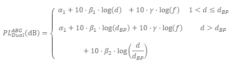
Where PL represents the propagation losses (Path Loss) with distance d. The parameters α and β allow the adjustment of the model and ALPHA-BETA-GAMMA MODEL (ABG) This model is based on the FI but adds a new parameter γ to take into account the variation with frequency:
In addition, it has a double slope option, in the case of an inflection point in the measurements at the distance dBP:
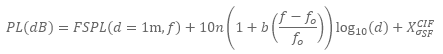
CLOSE-IN FREE SPACE REFERENCE MODEL (CI) The CI model is a simple model that only needs one parameter to describe path losses over all frequencies and distances. It is based on fundamental physical principles and can be used in links with or without direct vision. It is easy to implement with respect to current 3GPP models by means of a subtle modification, consisting of replacing the floating constant β with a frequency-dependent constant that represents the losses in free space in the first meter of distance:
The parameter α is now identified with the exponent n of the potential loss law (this parameter is commonly referred to as the Path Loss Exponent, PLE), since the propagation losses are proportional to dn when expressed in natural units. The parameter d0 is the distance anchor, usually equal to 1 m. The random variable CLOSE-IN FREE SPACE REFERENCE FREQUENCY DEPENDANT MODEL (CIF) Starting from the CI model, a new parameter b is incorporated that allows to contemplate a variation of the parameter n with the frequency, in relation to a reference frequency f0.
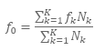
Where f0 is a reference frequency and can be calculated as:
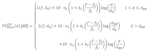
Where K is the number of unique frequencies, Nk is the number of measurement points corresponding to each unique frequency fk. Another possible approximation is to take f0 as the lowest frequency of the data [1]. This model also has a double slope variant:
REFERENCES [1] S. Piersanti, L.A. Annoni, and D. Cassioli, "Millimeter Waves Channel Measurements and Path Loss Models," in IEEE ICC 2012 - Wireless Communications Symposium, Otawa, Canada, 2012, pp. 4552-4556. [2] Aalto University et al., "5G Channel Model for bands up to 100 GHz," Technical Report, October 2016. http://www.5gworkshops.com/5GCM.html. [3] 3GPP. "Study on channel model for frequencies from 0.5 to 100 GHz," TR 38.901 v14.3.0, Dec. 2017. https://portal.3gpp.org/desktopmodules/Specifications/SpecificationDetails.aspx?specificationId=3173 [4] METIS, "METIS Channel Models," Deliverable D1.4 v3 Project Number ICT-317669, 2015. [5] mmMAGIC. (May, 2017). "Measurement Results and Final mmMAGIC Channel Models," H2020-ICT-671650-mmMAGIC/D2.2 v2.0. https://5g-mmmagic.eu/results/ [6] G.R. MacCartney Jr. and T.R. Rappaport, "Rural Macrocell Path Loss Models for Millimeter Wave Wireless Communications," IEEE Journal on Selected Areas in Communications, vol. 35, no. 7, pp. 1663-1678, July 2017. [7] T.S. Rappaport et al., "Overview of Millimeter Wave Communications for Fifth-Generation (5G) Wireless Networks - With a Focus on Propagation Models," IEEE Transactions on Antennas and Propagation , vol. 65, no. 12, pp. 6213-6230, December 2017. [8] ITU-R Report M.2135-1, "Guidelines for the evaluation of radio interface technologies for IMT-Advanced," ITU Radiocommunication Bureau, Geneva, Switzerland, 2009. [9] 3GPP, "Technical specification group radio access network; channel model for frequency spectrum above 6 GHz (Release 14)," 3rd Generation Partnership Project (3GPP) TR 38.900 v14.2.0 Dec. 2016. [10] Rec. ITU-R P. 1411-8, "Propagation data and prediction methods for the planning of short-range outdoor radiocommunication systems and radio local area networks in the frequency range 300 MHz to 100 GHz," ITU Recommendation Bureau, Geneva, Switzerland, 2015. |