 |
|
<< Pulse para mostrar la Tabla de Contenidos >> COST 231 |


|
|
|
<< Pulse para mostrar la Tabla de Contenidos >> COST 231 |
|
|
DESCRIPTION The COST 231 model [1-2] is a semi-empirical path loss model, resulting from the combination of Walfisch-Bertoni [3] and Ikegami [4] models. It is recommended for macro-cells in urban and suburban scenarios, showing very good results for path loss calculations for base station antennas located above the average roof height. However, the prediction errors increase significantly as transmitter antenna height approaches the roof height, reaching a very poor performance for transmitters located below that level. The COST 231 model has a frequency range between 800 MHz to 2000 MHz. Compared to previous models such as Okumura-Hata, the calculation procedure is more detailed, and includes four additional parameters, namely: •Buildings height. •Roads width. •Buildings separation. •Road orientation with respect to the direct radio path. The basic propagation loss, Lb, is calculated as the sum of three components: the free-space loss, L0; the roof-to-street loss, Lrts, produced in the street where the receiver is located, as result of the diffraction on the next rooftop; and the multiscreen diffraction loss Lmsd, produced by multiple diffractions on the building rooftops along the direct propagation path. The model also distinguishes LOS and NLOS situations. In general, the restrictions for the model are: •f = 800 – 2000 MHz •hb = 4 – 50 m (base station height) •hm = 1 – 3 m (mobile station height) •d = 0.02 – 50 km (distance between base station and mobile station) •Δhb > 0 m (base station height relative to roof-top level) DEVELOPMENT a) For LOS scenarios, path loss estimation considers only the free-space loss, Lb = L0(LOS) where:
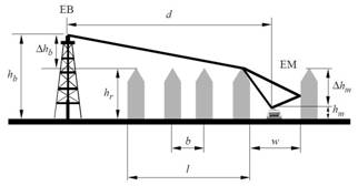
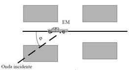
where d is expressed in km and f in MHz. b) The typical NLOS path described in the COST 231 model is represented in Figures 1a and 1b.
Figure 1a: Typical scenario of NLOS propagation used in the COST 231 model. Side view.
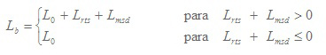
Figure 1b: Typical scenario of NLOS propagation used in the COST 231 model. Top view. The parameters defined in the COST 231 model are: •hr: average buildings height (m) •w: street width (m) •b: mean separation between buildings (m) •φ: orientation angle between the direction of propagation and street axis (degrees) •hb: base station antenna height (m) •hm: mobile station antenna height (m) •Δhm = hr – hm (m) •Δhb = hb – hr (m) •l: total distance between first and last buildings (m) •d: distance between base station and mobile station (km) •f: frequency (MHz) The basic propagation loss for the NLOS scenario is given by:
The propagation loss in free space conditions, L0, is obtained according to the expression:
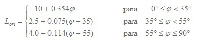
The term Lrts takes into account the street width and its orientation with respect to the propagation direction of the main beam. Its definition is based on the roof-to-street principles given by the Ikegami model [4]. The expression for Lrts calculation is accepted by the ITU-R Rec. 1411 [5] and is given by:
where:
The term Lori is a correction factor that accounts for the loss due to the orientation of the street. If the value of Lrts< 0, t must be considered Lrts = 0. The multiscreen diffraction loss, Lmsd, is a function of frequency, distance between the mobile station and the base station, as well as base station height and building heights. Like Lrts, if the value of Lmsd is negative, it is considered that Lmsd = 0. Its value is calculated using the expression:
where:
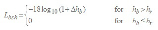
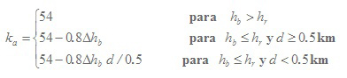
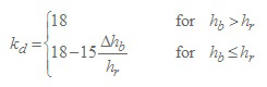
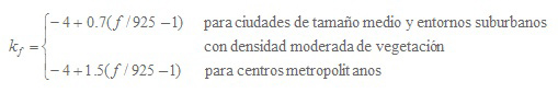
is a term that depends on base station height. Furthermore, the coefficients are defined:
The term ka represents the increase of path loss for base station antennas below the average height of the buildings. The terms kd and kf control the dependence of Lmsd on distance and frequency, respectively. In the case that no data were available about the buildings along the propagation path, the COST 231 model recommends using:
REFERENCES [1] E. Damosso, "Digital Mobile Radio: Towards Future Generation Systems", European Commission, Final Report of the COST 231 Project, Chapter 4, 1998. [2] L. M. Correia, "A view of the COST 231-Bertoni-Ikegami model," 2009 3rd European Conference on Antennas and Propagation, Berlin, 2009, pp. 1681-1685. [3] J. Walfisch and H. L. Bertoni, "A theoretical model of UHF propagation in urban environments," in IEEE Transactions on Antennas and Propagation, vol. 36, no. 12, pp. 1788-1796, Dec 1988. doi: 10.1109/8.14401 [4] F. Ikegami, T. Takeuchi and S. Yoshida, "Theoretical prediction of mean field strength for urban mobile radio," in IEEE Transactions on Antennas and Propagation, vol. 39, no. 3, pp. 299-302, Mar 1991. doi: 10.1109/8.76325 [5] ITU-R Recommendation P.1411-4, "Propagation data and prediction methods for the planning of short-range outdoor radiocommunication systems and radio local area networks in the frequency range 300 MHz to 100 GHz", ITU, Geneva, Switzerland, 2007. |