|
The tool for editing indoor cartography allows the user to define their own vector mapping layers to use in their indoor propagation simulations. The tool allows you to easily model the walls and floors by using the Xirio viewer or by importing an AutoCAD file.
The indoor cartography editor can be accessed by selecting the icon  from the user layers manager from the user layers manager  . .
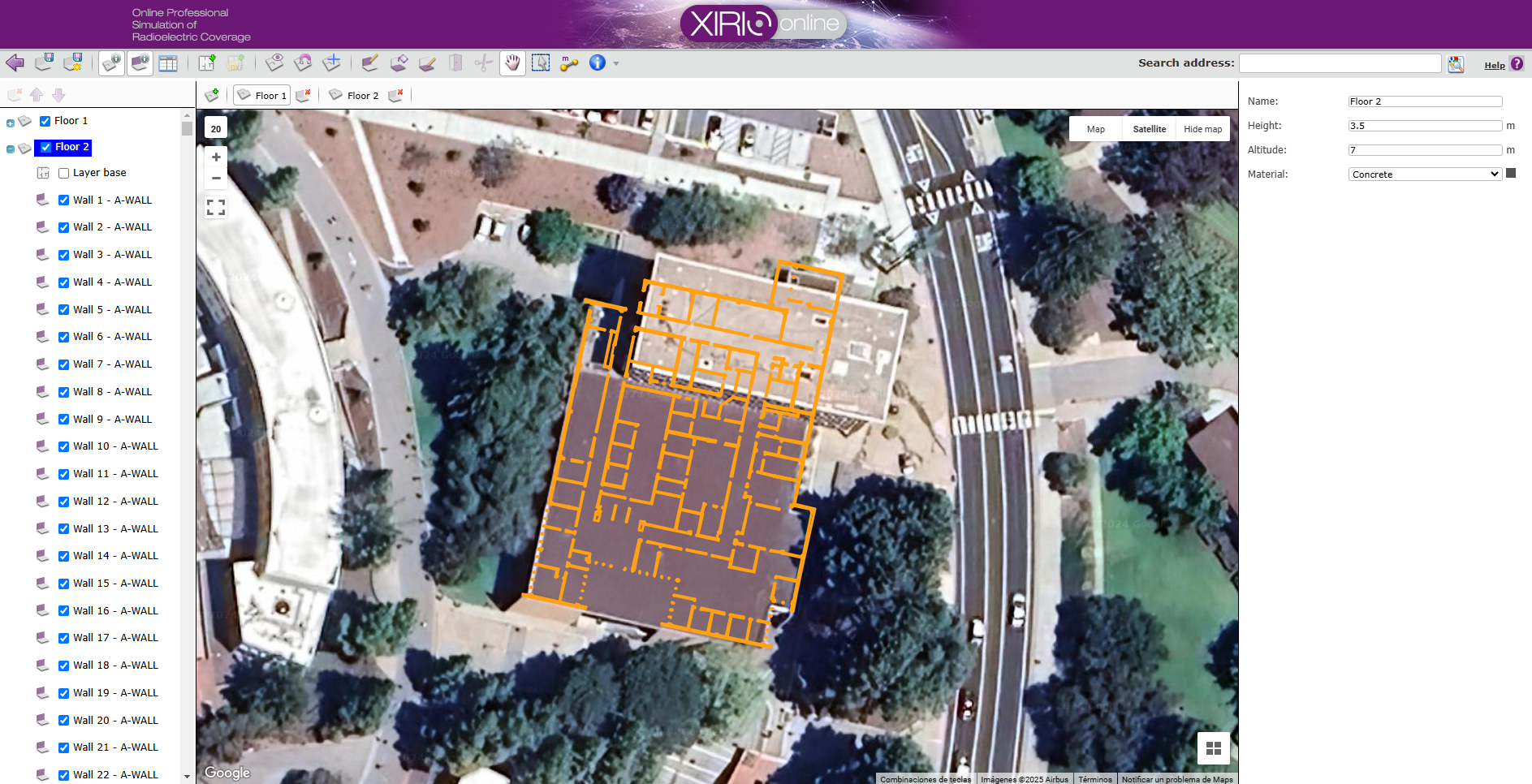
It will open a new window with a viewer and its own toolbar with all the necessary functionality to generate the walls and floors of the layer.
GENERAL OPTIONS
The icon  closes the editor window without saving the layer. The user will be asked for confirmation before closing the window. closes the editor window without saving the layer. The user will be asked for confirmation before closing the window.
The icon  saves the layer in the user's account. At this point the user will be prompted for a name and description for the layer. saves the layer in the user's account. At this point the user will be prompted for a name and description for the layer.
The icon  saves the layer as a new layer in the user's account. saves the layer as a new layer in the user's account.
The icon  shows or hides the left panel with the list of architectural elements (floors, walls and floors). shows or hides the left panel with the list of architectural elements (floors, walls and floors).
The icon  shows or hides the right panel with the information about the selected item. shows or hides the right panel with the information about the selected item.
The icon  opens the list of materials for the layer and their corresponding properties: name, color, losses, etc. opens the list of materials for the layer and their corresponding properties: name, color, losses, etc.
CREATE A NEW FLOOR
Selecting the icon  creates a new floor. This new item will appear in the left panel of architectural elements, along with all the walls and floors to be created later. In addition, when selecting this floor, in the right information panel we can configure its name, height, altitude, and floor material. creates a new floor. This new item will appear in the left panel of architectural elements, along with all the walls and floors to be created later. In addition, when selecting this floor, in the right information panel we can configure its name, height, altitude, and floor material.
The height of a floor is defined as the distance between the floor and the ceiling of the floor. In this way, the walls and ceilings that belong to a floor cannot exceed its height.
The altitude of the floor is defined as the height at which the ground of the floor is above street level.
A floor can be removed at any time by selecting the icon  . All walls and floors associated with the floor will be removed. . All walls and floors associated with the floor will be removed.
It is necessary to associate a base plane to the floor. By selecting the icon  , the user will be able to upload an image from his computer and georeference it on the Xirio viewer. The user can move the image, modify its size and rotate it until the image fits perfectly in its real position. This image will also be used as a visualization layer when returning to the planning tool and using this layer in the calculations. , the user will be able to upload an image from his computer and georeference it on the Xirio viewer. The user can move the image, modify its size and rotate it until the image fits perfectly in its real position. This image will also be used as a visualization layer when returning to the planning tool and using this layer in the calculations.
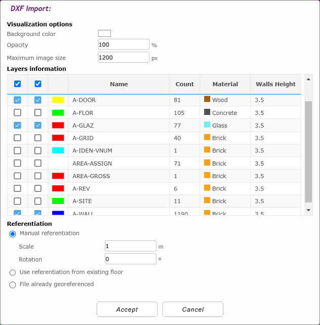
It is also possible to use a DXF file from AutoCAD by selecting the icon  , so that the user will obtain a whole design for the floor from the imported project without manually modelling the indoor layer. To select a file, it is necessary to previously upload it to the User files. , so that the user will obtain a whole design for the floor from the imported project without manually modelling the indoor layer. To select a file, it is necessary to previously upload it to the User files.
Before importing the file, the user will be allowed to check or uncheck the different elements in the file to consider them to be imported or not, and to select their properties.
DEFINE WALLS AND CEILINGS
Once a floor has been created, a new wall can be defined on the plan by selecting the icon  . Clicking successively on the viewer will create a polyline that will define the wall. To finish defining the wall you just have to double click or right click with the mouse on the viewer. . Clicking successively on the viewer will create a polyline that will define the wall. To finish defining the wall you just have to double click or right click with the mouse on the viewer.
By selecting this wall in the left panel, in the right information panel we can configure its name, height and material.
When creating a new wall, the height and material of the last wall generated are taken by default.
Finally, if the height of a wall is less than the height of the floor to which it belongs, an opening is created in which a diffraction effect could occur. It is advisable to use this mechanism to model false ceilings.
A new floor can be defined on the plan by selecting the icon  . Successively clicking on the viewer will create a polygon that will define the ground. To finish defining the floor, you just have to double click or right click with the mouse on the viewer. . Successively clicking on the viewer will create a polygon that will define the ground. To finish defining the floor, you just have to double click or right click with the mouse on the viewer.
By selecting this floor in the left panel, in the right panel of information we can configure its name.
The icons  and and  allows the user to sort the floor elements. allows the user to sort the floor elements.
DUPLICATE A FLOOR
When you have a floor already generated, if we select the icon again to add a second floor, the user can choose any of the existing floors to make a copy. In this way, the second floor will have the base plan, walls and floors of the copied floor.
In addition, when selecting the icon to upload a base plan for the new floor, a copy of the base plan of any of the existing floors can be made. The user can upload a new image and georeference it, duplicate the base plan of another floor, or upload a new floor taking advantage of the referencing of the plan of another floor. In the latter case, to obtain a satisfactory result, the images need to be the same size and match perfectly.
TOOLS
The icon  shows/hides the elements of the floor below the selected floor. Its transparency allows it to be used as a reference for drawing new items in the selected floor. shows/hides the elements of the floor below the selected floor. Its transparency allows it to be used as a reference for drawing new items in the selected floor.
The icon  enables/disables the magnetism drawing aid. Drawing new walls on the plane forces the position of the new wall vertices onto existing vertices or walls. enables/disables the magnetism drawing aid. Drawing new walls on the plane forces the position of the new wall vertices onto existing vertices or walls.
The icon  enables/disables the perpendicular drawing aid. Drawing new walls on the plane forces the position of the new vertices of the wall onto a position perpendicular to an existing wall. enables/disables the perpendicular drawing aid. Drawing new walls on the plane forces the position of the new vertices of the wall onto a position perpendicular to an existing wall.
The icon  helps to generate the floors using the existing walls as reference. Moving the cursor over the viewer highlights the proposed floor on the plan. By double clicking on the viewer, sections are added to complete the entire floor. helps to generate the floors using the existing walls as reference. Moving the cursor over the viewer highlights the proposed floor on the plan. By double clicking on the viewer, sections are added to complete the entire floor.
The icon  creates a door on a wall. Once selected, when moving the cursor over a wall, it transforms, indicating that it is possible to create an opening by clicking. At this time the user is required to enter the door size. The wall will split into two parts at the selected point. creates a door on a wall. Once selected, when moving the cursor over a wall, it transforms, indicating that it is possible to create an opening by clicking. At this time the user is required to enter the door size. The wall will split into two parts at the selected point.
The icon  releases the selected drawing tool and enables the drag tool to be used in the viewer. releases the selected drawing tool and enables the drag tool to be used in the viewer.
The icon  allows to select more than one element by dragging the cursor. allows to select more than one element by dragging the cursor.
The icon  allows to measure the distance and azimuth between two points by selecting one of the points and dragging the cursor to the other. allows to measure the distance and azimuth between two points by selecting one of the points and dragging the cursor to the other.
Finally, the user has a series of keyboard accelerators, which can be consulted by clicking  , and that can be activated just holding down the following keys: , and that can be activated just holding down the following keys:
•Ctrl: Adds an element to the selection
•Del: Deletes the selected item
•M: Activates the magnetism drawing aid
•O: Activates the perpendicular drawing aid
•A/0: Adds a vertex to a wall
•I: Inserts a vertex to a wall
•Q: Deletes a vertex of a wall
•Z: Disassociates vertices by clicking and dragging on the viewer
•U: Deletes the last vertex added on a wall
|