 |
|
<< Pulse para mostrar la Tabla de Contenidos >> REC. UIT-R P.526-15 |


|
|
|
<< Pulse para mostrar la Tabla de Contenidos >> REC. UIT-R P.526-15 |
|
|
DESCRIPCIÓN The ITU-R Recommendation P.526-15 [1] provides several models to evaluate the effect of diffraction on the received field strength. The models are applicable to different obstacle types and to various path geometries. DESARROLLO
Method for a general terrestrial path This model is based on the Bullington construction, but also makes use of the spherical Earth diffraction model. These models are combined so that for a completely smooth path, the result will be the same as the spherical Earth model. The method contains two sub-models: 1.the Bullington diffraction method used with a tapered correction to provide a smooth transition between LoS and trans-horizon; 2.the spherical Earth method.
Bullington model In the following equations slopes are calculated in m/km relative to the baseline joining sea level at the transmitter to sea level at the receiver. The distance and height of the i-th profile point are di km and hi m above sea level respectively, i takes values from 1 to n where n is the number of profile points, and the complete path length is d km. For convenience the terminals at the start and end of the profile are referred to as transmitter and receiver, with heights in m above sea level hts and hrs, respectively. Effective Earth curvature Ce km−1 is given by 1/re where re is effective Earth radius in km. Wavelength in metres is represented by λ. Find the intermediate profile point with the highest slope of the line from the transmitter to the point:
where the profile index i takes values from 2 to n − 1. Calculate the slope of the line from transmitter to receiver assuming an LoS path:
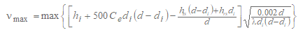
Two cases must now be considered. Case 1. Path is LoS If Stim < Str the path is LoS. Find the intermediate profile point with the highest diffraction parameter ν:
where the profile index i takes values from 2 to n − 1. In this case, the knife-edge loss for the Bullington point is given by:
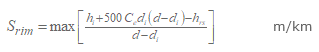
where the function J is given by the knife-edge single-obstacle diffraction model. Case 2. Path is trans-horizon If Stim ≥ Str the path is trans-horizon. Find the intermediate profile point with the highest slope of the line from the receiver to the point.
where the profile index i takes values from 2 to n − 1. Calculate the distance of the Bullington point from the transmitter:
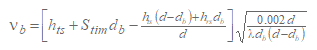
Calculate the diffraction parameter, νb, for the Bullington point:
In this case, the knife-edge loss for the Bullington point is given by:
For Luc calculated using either equation (4) or (8), Bullington diffraction loss for the path is now given by:
Complete method Use the Bullington method described above for the actual terrain profile and antenna heights. Set the resulting Bullington diffraction loss for the actual path, Lba dB, to Lb as given by equation (9). Find the effective transmitter and receiver heights relative to a smooth surface fitted to the profile. Calculate initial provisional values for the heights of the smooth surface at the transmitter and receiver ends of the path, as follows:
Find the highest obstruction height above the straight-line path from transmitter to receiver hobs, and the horizon elevation angles αobt, αobr, all based on flat-Earth geometry, according to:
where:
and the profile index i takes values from 2 to (n – 1). Calculate provisional values for the heights of the smooth surface at the transmitter and receiver ends of the path: If hobs is less than or equal to zero, then:
otherwise:
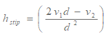
where:
Calculate final values for the heights of the smooth surface at the transmitter and receiver ends of the path: If hstp is greater than h1 then:
otherwise:
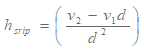
If hsrp is greater than hn then:
otherwise:
Use the method in § 4.5.1 for a smooth profile by setting all profile heights hi to zero, and with modified antenna heights:
Set the resulting Bullington diffraction loss for the smooth path, Lbs dB, to Lb as given by equation (9). Use the method for diffraction over spherical earth for the actual path length d km and with:
Let the resulting spherical-earth diffraction loss be Lsph dB. The diffraction loss for the general path is now given by:
REFERENCES [1] ITU-R Recommendation P.526-15, "Propagation by diffraction", ITU, Geneva, Switzerland, 2019. |