 |
|
<< Pulse para mostrar la Tabla de Contenidos >> ITU-R REC. P.530 |


|
|
|
<< Pulse para mostrar la Tabla de Contenidos >> ITU-R REC. P.530 |
|
|
DESCRIPTION The ITU-R Recommendation P.530 [1], provides a few propagation models useful for the evaluation of propagation effects in microwave radiocommunications systems. This Recommendation provides prediction methods for propagation effects that should be taken into account in the design of digital fixed line-of-sight links, both in clear-air and rainfall conditions. It also provides link design guidance in clear step-by-step procedures including the use of mitigation techniques to minimize propagation impairments. The final outage predicted is the base for other ITU-R Recommendations addressing error performance and availability. Different propagation mechanisms, with a variety of effects on the radio links, are addressed in the Recommendation. Ranges of prediction methods application are not always coincident. A brief description of the implemented prediction methods is given in the following sections.
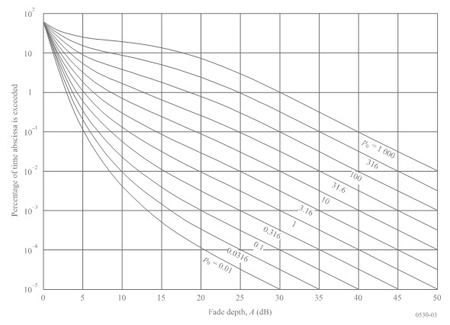
Fading due to multipath and related mechanisms Fading is the most important mechanism that affects the performance of digital radio links. Multipath in the troposphere can cause deep fades, especially in longer paths or at higher frequencies. The prediction method for all percentages of time is graphically illustrated in figure 1. For small percentages of time, fading has a Rayleigh distribution, with an asymptotic variation of 10 dB per probability decade. This can be predicted by the following expression:
•K: geoclimatic factor. •dN1: point refractivity gradient in the lowest 65 m of the atmosphere not exceeded for 1% of an average year. •sa: area terrain roughness, defined as the standard deviation of terrain heights (m) within a 110 km x 110 km area with a 30 s resolution. •d: link path distance (km). •f: link frequency (GHz). •hL: altitude of the lower antenna above sea level (m). •|εp|: absolute value of the path inclination. •p0: multipath occurrence factor. •pw: percentage of time fade depth A is exceeded in average worst month.
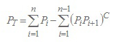
Figura 1:Percentage of time, pw, fade depth, A, exceeded in average worst month, with p0 ranging from 0.01 to 1000 If A is made equal to the receiver margin, the probability of link outage due to multipath propagation is equal to pw /100. For a link with n digital hops, the probability of outage PT takes into account the possibility of a small correlation between fades in consecutive digital hops.
In (4),
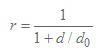
Attenuation due to hydrometeors Rain can cause very deep fades, particularly at higher frequencies. The Rec. P. 530 includes the following simple technique that may be used for estimating the long-term statistics of rain attenuation: Step 1: Obtain the rain rate R0.01 exceeded for 0.01% of the time (with an integration time of 1 min). Step 2: Calculate the specific attenuation, γR (dB/km) for the frequency, polarization and rain rate of interest using Recommendation ITU-R P.838. Step 3: Compute the link effective path length, deff, by multiplying the actual path length d by a distance factor r. An estimation of this factor is given by:
where: for R0.01 ≤ 100 mm/h:
For R0.01 > 100 mm/h, use the value 100 mm/h in place of R0.01. Step 4: An estimation of the path attenuation exceeded for 0.01% of the time is given by:
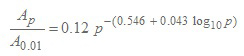
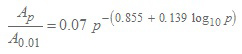
Step 5: For radio links located in latitudes equal to or greater than 30° (North or South), the attenuation exceeded for other percentages of time p in the range 0.001% to 1% may be deduced from the following power law:
Step 6: For radio links located at latitudes below 30° (North or South), the attenuation exceeded for other percentages of time p in the range 0.001% to 1% may be deduced from the following power law.
The formulas (8) and (9) are valid within the range 0.001% - 1%. For high latitudes or high link altitudes, higher values of attenuation may be exceeded for time percentage p due to the effect of melting ice particles or wet snow in the melting layer. The incidence of this effect is determined by the height of the link in relation to the rain height, which varies with geographic location. A detailed procedure is included in the Recommendation [1]. The probability of outage due to rain is calculated as p / 100, where p is the percentage of time rain attenuation exceeds the link margin.
Reduction of cross-polar discrimination (XPD) The XPD can deteriorate sufficiently to cause co‑channel interference and, to a lesser extent, adjacent channel interference. The reduction in XPD that occurs during both clear-air and precipitation conditions must be taken into account. The combined effect of multipath propagation and the cross-polarization patterns of antennas governs reductions in XPD occurring for small percentages of time in clear-air conditions. To compute the effect of these reductions in link performance a detailed step-by-step procedure is presented in the Recommendation [1]. The XPD can also be degraded by intense rain presence. For paths on which more detailed predictions or measurements are not available, a rough estimate of XPD unconditional distribution can be obtained from a cumulative distribution of co-polar attenuation (CPA) for rain (see section 3), using the equi-probability relation:
The coefficients U and V(f) in general depends on a number of variables and empirical parameters, including frequency, f. For line-of-sight paths with small elevation angles and horizontal or vertical polarization, these coefficients may be approximated by:
An U0 average value of about 15 dB, with a lower bound of 9 dB for all measurements, has been obtained for attenuations greater than 15 dB. A step-by-step procedure is given to calculate the outage due to XPD reduction in the presence of rain proposed in ITU-R Rec. 530 [1].
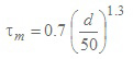
Distortion due to propagation effects The primary distortion cause on line-of-sight links in UHF and SHF bands is the frequency dependence of amplitude and group delay during clear-air multipath conditions. The propagation channel is most often modeled by assuming that the signal follows several paths, or rays, from transmitter to receiver. Performance prediction methods make use of such a multi-ray model by integrating many variables such as delay (time difference between the first arrived ray and the others) and amplitude distributions along with a proper model of equipment elements such as modulators, equalizer, forward‑error correction (FEC) schemes, etc.. The method recommended in [1] for predicting error performance is a signature method. he outage probability is here defined as the probability that BER is larger than a given threshold. The calculation method is described below: Step 1: Calculate the mean time delay from:
where: d is the path length (km). Step 2: Calculate the multipath activity parameter η as:
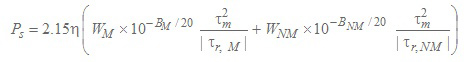
Step 3: Calculate the selective outage probability from:
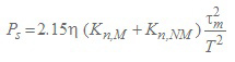
where: •Wx: signature width (GHz) •Bx: signature depth (dB) •tr,x: the reference delay (ns) used to obtain the signature, with x denoting either minimum phase (M) or non-minimum phase (NM) fadings. If only the normalized system parameter Kn is available, the selective outage probability in equation (15) can be calculated by:
where: •T: system baud period (ns) •Kn,x: the normalized system parameter, with x denoting either minimum phase (M) or non-minimum phase (NM) fadings.
Diversity techniques There are a few techniques available for alleviating effects of flat and selective fading, most of which alleviate both at the same time. The same techniques often alleviate reductions in cross-polarization discrimination also. Diversity techniques include space, angle and frequency diversity. Space diversity helps to combat flat fading (such as caused by beam spreading loss, or by atmospheric multipath with short relative delay) as well as frequency selective fading, whereas frequency diversity only helps to combat frequency selective fading (such as caused by surface multipath and/or atmospheric multipath). Whenever space diversity is used, angle diversity should also be employed by tilting antennas at different upward angles. Angle diversity can be used in situations in which adequate space diversity is not possible or to reduce tower heights. The improvement degree afforded by these techniques depends on the extent to which the signals in the system diversity branches are uncorrelated. The diversity improvement factor, I, for fade depth, A, is defined by:
where: pd(A) is the percentage of time in the combined diversity signal branch with fade depth larger than A and p(A) is the percentage for the unprotected path. The diversity improvement factor for digital systems is defined by the ratio of exceedance times for a given BER with and without diversity. The improvement due to the following diversity techniques can be calculated: •Space diversity. •Frequency diversity. •Angle diversity. •Space and frequency diversity (two receivers). •Space and frequency diversity (four receivers). The detailed calculations can be found in [1].
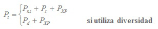
Prediction of total outage The total outage probability due to clear-air effects is calculated as:
•Pns: Outage probability due to non-selective clear-air fading (Section 2). •Ps: Outage probability due to selective fading (Section 5). •PXP: Outage probability due XPD degradation in clear-air (Section 4). •Pd: Outage probability for a protected system (Section 6). The total outage probability due to rain is calculated from taking the larger of Prain and PXPR. •Prain : Outage probability due to rain fading (Sección 3). •PXPR : Outage probability due XPD degradation associated to rain (Sección 4). The outage due to clear-air effects is apportioned mostly to performance and the outage due to precipitation, predominantly to availability. REFERENCES [1] ITU-R Recommendation P.530-16, "Propagation data and prediction methods required for the design of terrestrial line-of-sight systems", ITU, Geneva, Switzerland, 2015. |