 |
|
<< Pulse para mostrar la Tabla de Contenidos >> SYNAPSE: GRAPH DATA |


|
|
|
<< Pulse para mostrar la Tabla de Contenidos >> SYNAPSE: GRAPH DATA |
|
|
The principle behind the graphs component The graphs component is only effective for transmitters for which the vectors geographic data are available over the entire calculation zone. In a micro cellular context, the emitting and receiving antennas are positioned below the average level of the rooftops. In this case, the signal strength received by diffraction above the rooftops is significantly inferior to that of the signal strength received by propagation in the street and diffraction on the edges. The propagation hypothesis above the rooftops is therefore no longer sufficient, especially when the number of edges between the transmitter and receiver is not too great.
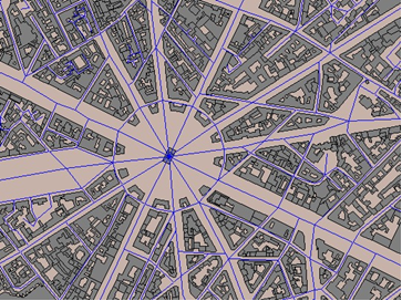
When the antenna is well under the rooftops, the electro-magnetic propagation occurs principally along the streets which act as street canyons. There is a "guiding" phenomenon of the electro-magnetic waves by the street which implies that the major propagation phenomena are situated in the horizontal plane and no longer the vertical plane, as is the case with the profile models. Thus, we benefit from the canalization effect to increase propagation. To model this guiding phenomenon of the electro-magnetic waves by the streets, the model uses a graph of the street axes. A graph is formed by arcs representing the axes of the streets capable of acting as a wave guide.
Searching the graphs is done using the graphs index parameter in which are defined the files that contain the relative information used to model the route maintenance.
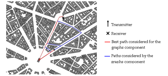
The modelling and function of the graphs component This component is responsible for calculating all the contributions coming from the receiver by the different paths illustrated by the graph. It calculates the loss for each path as a result of distance, of the diffraction on the vertical ridges formed by street corners, and of multiple reflections along the street axes. All the elementary contributions are then added to constitute the total loss of the graphs component representing the electro-magnetic energy that propagates along the streets. The number of paths going from the transmitter to the receiver is not defined. Only those paths for which the loss is less than a defined threshold, that is to say sufficiently significant, are selected.
The profile loss is calculated and is added to the graphs component loss to form the total loss of Synapse. |