 |
|
<< Pulse para mostrar la Tabla de Contenidos >> SYNAPSE: THE MULTIPATH COMPONENT |


|
|
|
<< Pulse para mostrar la Tabla de Contenidos >> SYNAPSE: THE MULTIPATH COMPONENT |
|
|
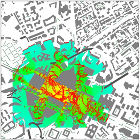
Description The multipath component aims at providing more accurate path loss predictions in dense urban environments thanks to the simulation of spatiotemporal diversity. To do so, it relies on a deterministic identification of the main propagation paths between the transmitter and the receivers. This is achieved by simulating the propagation of a Dirac impulse signal and its subsequent interactions with terrain and surface features.
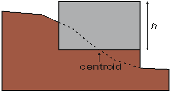
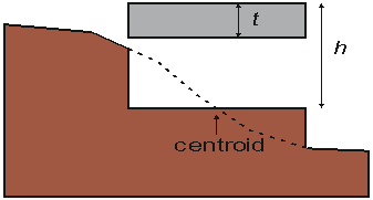
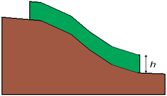
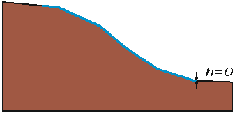
The multipath component requires polygons and height data to model a specific 3D geographical environment. It cannot be activated if either is missing. The polygons are extruded according to their class, height and thickness (if applicable) and are assigned the corresponding material properties (no reflection nor diffraction on vegetation, no transmission through water or ground, specific permittivity on buildings, and so on). The figures below detail how the polygons are extruded on top of terrain. The height is denoted by h and the thickness by t.
Extrusion of buildings, bridges, vegetation and water surfaces
In addition, the multipath component also offers the possibility to describe a scheme with which a particular 2D shape should be extruded and so allows modeling 3D objects more accurately thus giving better simulations. Electromagnetic waves are modeled through its electrical compound. It is a three-dimensional vector which initial value is given by the transmitter's antenna configuration. The orientation in space is set by the polarization whereas the magnitude is set by the transmitted power. Polarization, magnitude, phase and delay are then tracked as the wave propagates. Any interaction with a geographical feature triggers one or more of the following phenomena: reflection, transmission and diffraction. Each one of them alters polarization, magnitude and phase shift depending on the electromagnetic properties assigned to the class of the geographical feature and in a consistent way with the other Synapse model components. In the end, all the identified propagation paths are combined to produce a correction applied to the main Synapse Model path loss simulation. Four multipath variables (see below) are also derived from them to further describe how the energy is received at each receiver.
Multipath variables While path loss is the core metric behind any modern mobile network design, it does not account for the propagation paths that are exploited by multi-antenna technologies. Hence, deriving MIMO throughputs from this sole value is error prone. The four additional metrics simulated by the multipath component aim at providing MIMO context for more accurate throughput predictions and, in the end, guidance on choosing the correct MIMO antenna configuration. •Rice Factor. It is a value that indicates how close a receiver is from line of sight conditions. Negative values mean that the area receives energy from many dominant paths and is usually a good candidate for MIMO optimisations. •Delay-Spread. It measures the time span during which most of the energy arrives at a receiver. A maximum value is provided by guard intervals and it is not expected to encounter delay-spreads that come close to this value. The lower the delay-spread the more opportunity there is for MIMO optimisations. •Angle-Spread. It measures the dispersion of the paths before they focus on the receiver. It is calculated at the transmitter's side and exclusively on the horizontal plane. It is a weighted circular standard deviation. Low values make massive MIMO possible. •MIMO Rank. It is the number of parallel streams achievable by a MIMO system. This value is simulated regardless of the actual MIMO configuration and maybe be as high as 32. |