 |
|
<< Pulse para mostrar la Tabla de Contenidos >> SECTOR LTE PARAMETERS |


|
|
|
<< Pulse para mostrar la Tabla de Contenidos >> SECTOR LTE PARAMETERS |
|
|
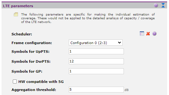
All LTE sector parameters, are initially configured by default when selecting the study service (technology), with the appropriate values for the simulation type to perform. It is recommended, to be reviewed and specified by the user to adapt their simulation to reality of the equipment that is trying to simulate.
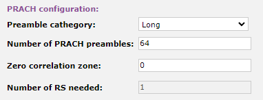
•Scheduler: The algorithm implemented by the scheduler distributes the LTE channel resources (frequency and time) dynamically between users of the system. In Xirio there are three kinds of scheduler theoretical algorithms for capacity calculations: Proportional Fair, Round Robin and Maximum Rate. •Frame Configuration: Allows to select the frame structure type. This parameter is only taken into account in LTE-TDD services. Since the same frequency is used in the TDD service for both downlink and uplink, the base station of the sector and the terminal need to change from transmission to reception and vice versa. The change between downlink and uplink occurs in the special subplot, composed of 14 symbols and divided into three parts: a downlink part (DwPTS), a guard period (GP), and a part for uplink (UpPTS). While the DwPTS part of the special subframe is used for data transmission, the UpPTS part does not because its short duration. In contrast, UpPTS can be used to evaluate channel characteristics or as an extra guard time. •UpPTS Symbols: Number of symbols dedicated to uplink within the special subframe. This value does not affect uplink calculations; only in downlink, since they are symbols not available for downlink. •DwPTS Symbols: Number of symbols dedicated to downlink within the special subframe. •GP Symbols: Number of dedicated save period symbols for switching between downlink and uplink transmission and vice versa. In these symbols there is no data transmission. •HW compatible with 5G: In order for a 5G sector that is not Stand-Alone to be able to provide service, it needs the support of a 4G station with 5G compatible hardware. This parameter is only available for LTE-A. •Aggregation threshold: The SINR threshold required for carrier aggregation to occur. This parameter is only available for LTE-A. PRACH CONFIGURATION The PRACH is the physical random access channel that mobile terminals use to ask base stations for resource allocation on the uplink communication.
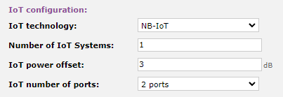
•Preamble cathegory: Preambles can be of two types, long or short. •Number of PRACH preambles: Number of possible sequences to be configured in the sector. •Zero correlation zone: Indicates the maximum expected symbol delay in the cell, that is, the length that is applied in the cyclic shifts to avoid ambiguities. •Number of RS needed: The number of RSs needed to get all the necessary preambles. IoT CONFIGURATION Configure the sector compatibility with IoT technology.
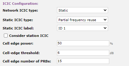
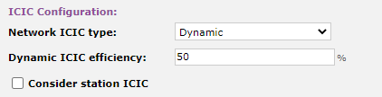
•IoT technology: It can be LTE-M or NB-IoT. •Number of IoT systems: Sets the number of resources to be dedicated to IoT. •IoT power offset: Indicates the power variation in the resources used by IoT with respect to those of LTE. •IoT number of ports: The number of antenna ports used by the IoT system. ICIC CONFIGURATION The main objective of the inter-cell interference coordination (ICIC), is to avoid high interference due to users located at the edges of adjacent cells. It can be static or dynamic.
Static ICIC The resources used by each cell are preset. Xirio provides different frequency reuse schemes based on the location of users on the center or on the edge of the cell.
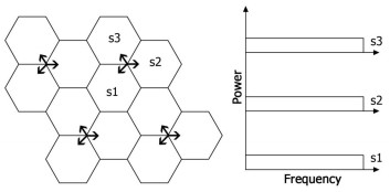
•Static ICIC type: The user can simulate the following frequency reuse schemes [1]:
- Frequency Reuse of 1, FR1
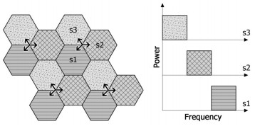
- Frequency Reuse of 3, FR3
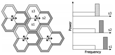
- Partial Frequency Reuse, PFR
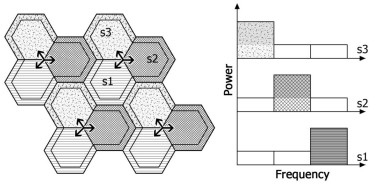
- Soft Frequency Reuse, SFR
•Static ICIC label: The static ICIC label defines the resource group that a base station dedicates to users in the cell border, therefore, two stations who share the same static ICIC label, spend the same resources to their users. This parameter is configurable only for the FR3, PFR and SFR schemes. •Consider station ICIC: When this option is selected, it is considered that the sectors that belong to the same station do not interfere with each other. This occurs by preventing the resources required at the edge of the cell from being used by more than one sector of the station. When sector stations are being simulated, each sector should use a different ICIC static label. •Cell edge power (%): This parameter sets the amount of power dedicated to resources for users at the cell edge. It is configurable only for PFR and SFR schemes. •Cell edge threshold: It determines whether a user is in the center or the edge of the cell. It is considered that the user is in the center of the cell when the margin of the desired signal with respect to the interferent is bigger than this value. Otherwise it is considered that the user is on the edge. It is configurable only for PFR and SFR schemes. •Cell edge number of PRBs: The number of PRBs (Physical Radio Blocks) reserved for the cell edge. This parameter is only configurable for PFR schemes. The frequency reuse schemes in Xirio-Online only use 3 sectors so this parameter must be a multiple of three. The following table shows the total usable number of PRBs for different bandwidths:
Dynamic ICIC The resources used by each cell are evaluated dynamically to improve inter-cell interference.
•Dynamic ICIC efficiency (%): It is posible to manage the resources in a totally dynamic way instead of a static way. This is an improvement of the intercellular interference present in the communications. Dynamic ICIC efficiency defines this interference reduction, taking values from 0% (the whole signal is considered interfering) up to 100% (no interference). DOWNLINK PARAMETERS
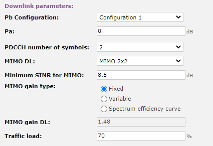
•Pb Configuration: In LTE there are some resources that can be assigned more power, typically the reference signals (RS). This is achieved by a power offset that establishes a relationship between the power allocated to the traffic channels and the signals allocated to the RS. The following table summarizes this power ratio for different configurations available in Xirio:
•Pa: Relation between the PDSCH power in symbols without reference signal (RS) with respect to RS itself. This value is given in dB.
•PDCCH number of symbols: Indicates the number of symbols dedicated to the control channel per subframe. For bandwidths from 3 MHz to 20 MHz it can take the values 1, 2 or 3. For 1.4 MHz it can take the values 2, 3 or 4. This is because fewer subcarriers in frequency domain requires more space in time domain. •MIMO: Enables or disables the use of MIMO. In Xirio-Online the options MIMO 2x2 and 4x2 are available. The use of these techniques allows to obtain very high data rates by using multiple channels in parallel. •MIMO Gain: This parameter quantifies the gain in the case of using MIMO techniques. •Consider gain by antenna diversity: If enabled, the antenna diversity gain will be included according to the selected MIMO configuration. •Traffic load (%): It defines the percentage of all available resources used in the sector. This parameter is used to model the effect of cell interference between stations. In Xirio results are offered to study three scenarios: - Stations with no load (0 %) - Stations with load defined by user - Stations at full load (100 % Xirio uses this parameter to calculate the SINR interference . If the user does not have estimations of this value, it is recommended to set it at 100%, for the worst case scenario. After performing a calculation of the capacity, the user will obtain traffic load values that will feed back SINR interference calculations, obtaining a final coverage estimation. UPLINK PARAMETERS
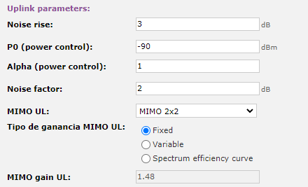
•Noise increase: This parameter quantifies the interference received at the base station in the upstream. •P0 and α (power control): The power transmitted by the mobile terminal is limited, due to a power control mechanism, to a value of P0 + α · PLDL, where PLDL are looses along the path, α is the compensating factor for these losses and P0 is the desired power at the base station which is obtained from the objetive SINR defined by the user. •Noise factor (dB): Noise factor of the sector. •MIMO UL: Allows you to enable or disable the use of MIMO in the upward direction in the case of LTE-A. 1x2, 1x4, 1x8, 2x2, 2x4, 2x8, 4x4, and 4x8 MIMO options are available in Xirio. The use of this type of technique allows obtaining high rates of data in the upward direction. •MIMO UL Gain: This parameter quantifies the gain obtained in the case of using MIMO techniques in the ascending direction for the case of LTE-A. REFERENCES [1] 4GPP, WP4, "Inter-Cell Interference Coordination".
| ||||||||||||||||||||||||||||||||