 |
|
<< Pulse para mostrar la Tabla de Contenidos >> MODULATIONS |


|
|
|
<< Pulse para mostrar la Tabla de Contenidos >> MODULATIONS |
|
|
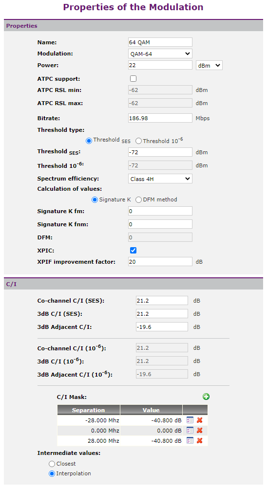
Parameters that characterize a modulation by radio equipment are shown in the following image:
In this dialog, if permissions are available, the user can configure advanced parameters of each equipment modulation:
•Threshold type: oThreshold for 10-6 BER. It is the reception threshold for not exceeding a bit error rate for which seconds have many errors (segundos que de 10-6 medida con un tiempo de integración de un segundo). oThreshold for a SES BER (Severely Errored Second). It is the reception threshold for not exceeding a bit error rate for which seconds have many errors (seconds with ≥ 30% of blocks with errors or at least one defect). This threshold depends on the digital frame structure sent in the radio link; Therefore it is not usually supplied by the manufacturer.
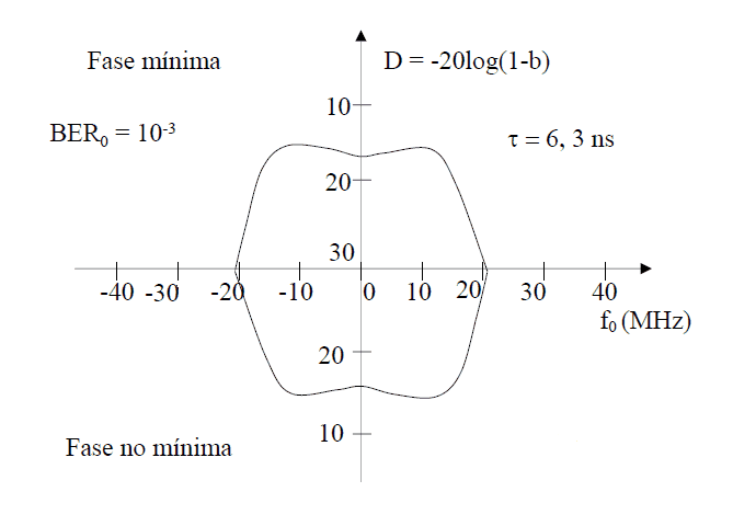
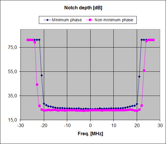
oK value, which is calculated from width and depth signature values and the reference delay, in addition to: ▪K signature value for minimum phase. ▪K signature value for not minimum phase
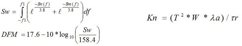
oUsing DFM (Dispersive Fade Margin), whose value is calculated according to the following formulas:
In addition, the modulation dialog also has a C/I section where the user can indicate: •relación Carrier / Interference ratio calculation: oCo-channel SES C/I, to ensure SES BER with a degradation of 1 dB threshold. oAdjacent SES channel C/I, to ensure SES BER with a degradation of 3 dB threshold. o3dB SES Co-channel C/I, to ensure SES BER with a degradation of 3 dB threshold. It is the margin which indicates whether a co-channel signal will interfere. o10-6 BER Co-channel C/I , to ensure 10-6 BER with a degradation of 1 dB threshold. oAdjacent 10-6 BER channel C/I, to ensure 10-6 BER with a degradation of 3 dB threshold. o3dB 10-6 BER Co-channel C/I, to ensure 10-6 BER with a degradation of 3 dB threshold. It is the margin which indicates whether a co-channel signal will interfere.
|