 |
|
<< Pulse para mostrar la Tabla de Contenidos >> ANTENNA |


|
|
|
<< Pulse para mostrar la Tabla de Contenidos >> ANTENNA |
|
|
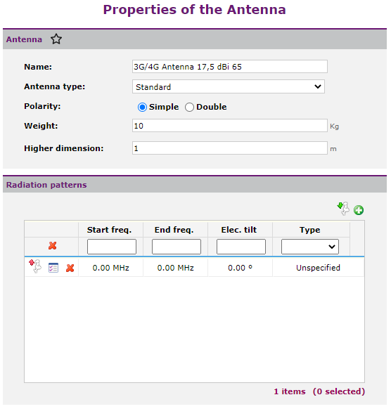
An antenna is a radio-electric device that emits or receives electromagnetic waves, which means it transforms electrical signals into electromagnetic waves and vice versa. In Xirio, an antenna is defined by a gain and a co-polar radiation pattern which it is formed by a horizontal diagram and one or more vertical diagrams. To create the antenna the user can either create it from a catalog element or create a new one. In the first case, a copy of the selected catalog element will be loaded, so that modifying this copy will not result in a modification of the original element in the catalog. Next image displays the window related to antenna components:
In the antenna dialog the user can configure the antenna's parameters: •Name. •Antenna type: Standard, AAS or Beamforming •Polarity: Single or Double. •Weight. •Larger Antenna Dimension.
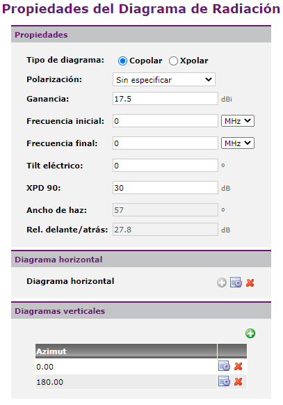
The user can add all radiation diagrams he wants. It is necessary to include at least one copolar diagram. If the antenna is used to emit at different polarities and the radiation diagram varies from one to another, it is advisable to add a Copolar diagram in H and another in V or XPIC. It is also necessary to add a crossedpolar (Xpolar) diagram if want to evaluate possible interferences received in cross polarization; if it does not exist, the XPD value of the copolar diagram is used. You can also enter the data from an antenna using a text file with Sirenet format using Radiation diagrams can be modified using
In the radiation diagram dialog, the administrator user can configure the parameters of the same: •Type of diagram: Copolar or Crosspolar. •Polarization: Unspecified (same diagram for all polarizations), Vertical, Horizontal, XPIC. •Gain. •Initial and final frequencies of diagram validity. Xirio selects the appropriate diagram depending on emission frequency of the radiating element. •XPD 90. Cross-polarization discrimination. •Beamwidth to 3dB. This parameter is informative and not editable, is obtained from horizontal diagram values. •Radiaton pattern Front/back ratio. This parameter is informative and not editable, is obtained from horizontal diagram values. •Antenna horizontal diagram. •Vertical Diagrams. The user must add, at least, one vertical diagram.
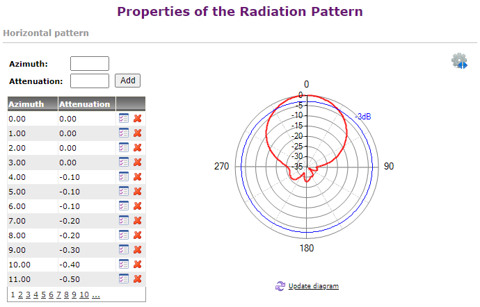
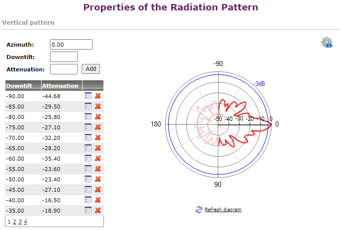
The dialog of vertical or horizontal diagrams is as follows:
In this dialog, the user can add, modify or delete points in the diagram and check their effects on the adjacent graph by clicking on "Refresh diagram". A horizontal diagram is defined by specifying a series of azimuth values (in degrees) and an attenuation (in dB) for each azimuth; a vertical diagram for a given azimuth (in degrees) is defined by specifying a series of inclination values (in degrees) and an attenuation (in dB) for each inclination. The values of the radiation diagrams are normalized, i.e. an attenuation equal to "0" corresponds to the highest gain value of the same. In addition, in the right part of the interface a toolbox with different functionalities is included that allow the interaction with the graph. These features allow you to change the coordinates of the diagram (representation in polar or Cartesian) and the scale (natural units or logarithmic scale), change the ranges of the axes to zoom in on the graph, show / hide the -3dB line and grids of each of the axes, and change the spacing interval of the axle grids. In the case of the vertical polar diagram, it can be seen that the back of the diagram is also represented (in a faded color), as long as its diagram is defined with the corresponding azimuth.
|